

The P0107 code indicates that the engine control module (ECM) or powertrain control module (PCM) has detected an abnormally low electrical input from the manifold absolute pressure (MAP) or barometric pressure (BARO) sensor circuit.
The MAP sensor provides information about intake manifold pressure, helping the engine computer calculate engine load and manage fuel delivery and ignition timing.
When the monitored signal falls below the expected electrical threshold, the computer may store P0107 and illuminate the check engine light.
However, P0107 does not automatically mean the MAP sensor has failed. Damaged wiring, a short to ground, connector problems, or an electrical supply fault may also be responsible.
This guide explains the meaning of P0107, its symptoms, likely causes, and a structured approach to diagnosing and repairing the fault.
What Does the P0107 Code Mean?
P0107 is a generic OBD-II diagnostic trouble code commonly described as Manifold Absolute Pressure/Barometric Pressure Circuit Low Input.
The code indicates that the ECM or PCM has detected an electrical input below the expected threshold in the monitored MAP/BARO circuit.
On many vehicles, a MAP sensor measures absolute pressure inside the intake manifold.
The engine computer uses this information, together with other sensor inputs, to determine engine operating conditions.
However, the exact circuit arrangement varies. Some vehicles use separate MAP and BARO sensors, while others use integrated or shared pressure-sensing arrangements.
What Does Low Input Mean?
Low input refers to the electrical signal monitored by the engine computer.
It does not automatically mean that actual intake manifold pressure is too low.
On a conventional analog MAP sensor, the signal voltage generally changes with manifold absolute pressure.
A short to ground, defective sensor, or other electrical problem can cause the signal to remain below its expected range.
Other sensor technologies and circuit designs may operate differently.
Always consult vehicle-specific service information before interpreting voltage values.
Is P0107 the Same as P0105 or P0108?
No.
Although these codes involve related pressure-sensor circuits, their fault descriptions differ.
P0105: MAP/BARO pressure circuit malfunction.
P0107: MAP/BARO pressure circuit low input.
P0108: MAP/BARO pressure circuit high input.
The correct diagnostic procedure depends on the code, vehicle design, and test results.
Common Symptoms of the P0107 Code
Check Engine Light
An illuminated check engine light is the most common indication of P0107.
The code may appear alone or alongside other pressure-sensor, reference-voltage, or engine-management codes.
Rough Idle
Incorrect MAP information may affect engine load calculations and fuel-control decisions.
Depending on the vehicle’s control strategy, this can contribute to unstable or rough idling.
However, rough idle has many possible causes and does not independently confirm a MAP circuit problem.
Hesitation During Acceleration
Some vehicles may hesitate or respond poorly to accelerator input when MAP information is unavailable or implausible.
The severity depends on how the engine computer responds to the detected fault.
Reduced Engine Power
A vehicle may experience reduced power if the ECM enters a fallback or protective operating strategy.
This is not guaranteed for every vehicle with P0107.
Stalling or Starting Problems
In some applications, incorrect pressure information can contribute to stalling or difficult starting.
Other stored codes and relevant engine conditions should be investigated before attributing these symptoms solely to P0107.
No Noticeable Driving Symptoms
Some vehicles may continue to operate with few obvious symptoms.
The engine computer may substitute calculated values or use other available sensor information.
Even when the vehicle appears to drive normally, the underlying circuit fault should be diagnosed.
Common Causes of the P0107 Code
1. Faulty MAP or BARO Sensor
An internal sensor failure may cause the monitored output to remain below its expected range.
However, a low signal alone does not prove that the sensor is defective.
The sensor should be tested according to the manufacturer’s diagnostic procedure before replacement.
2. Signal Wire Shorted to Ground
A damaged signal wire may contact ground or another low-voltage circuit.
This can pull the monitored sensor signal below the expected threshold and trigger P0107.
Possible sources include damaged insulation, wiring abrasion, or previous repair damage.
3. Open or Damaged Sensor Wiring
Depending on the circuit design, an open signal wire or damaged connection may cause the ECM to detect a low input.
The exact behavior depends on internal circuit arrangements and monitoring logic.
4. Missing or Incorrect Reference Voltage
Many conventional MAP sensors require a regulated reference-voltage supply.
If the reference supply is missing or pulled low, the sensor may be unable to produce a valid output.
A shared reference-voltage problem may also affect other sensors and produce additional trouble codes.
Reference-voltage specifications vary by vehicle.
5. Sensor Ground or Low-Reference Circuit Problems
A damaged low-reference connection can disrupt sensor operation.
Depending on the circuit design, this may produce abnormal readings or related diagnostic codes.
Do not assume that every ground fault produces a low signal.
Test the relevant circuit using the manufacturer’s wiring diagram.
6. Loose or Corroded Electrical Connector
Corrosion, moisture intrusion, damaged terminals, or a loose connector can interrupt the sensor’s electrical connection.
Intermittent faults may occur only during vibration, temperature changes, or particular driving conditions.
7. Rare ECM or PCM Circuit Failure
An internal engine computer fault is possible but uncommon.
Before considering ECM or PCM replacement, confirm that the sensor, reference supply, wiring, connectors, and related circuits have been tested correctly.
P0107 alone does not establish a failed control module.
Are Vacuum Leaks or Airflow Restrictions Causes of P0107?
Vacuum leaks, clogged air filters, and exhaust restrictions can affect engine operation and manifold pressure.
However, they are not typical direct explanations for a MAP/BARO electrical low-input code.
A vacuum leak may alter manifold pressure readings while the sensor circuit remains electrically functional.
Likewise, airflow or exhaust restrictions may cause performance complaints or other diagnostic codes without causing P0107.
If the vehicle has symptoms suggesting these problems, investigate them separately.
Do not replace an air filter, repair a vacuum leak, or replace exhaust components solely because P0107 is stored.
How to Diagnose the P0107 Code
A reliable diagnosis begins with verifying the fault and examining electrical evidence before replacing components.
Step 1: Verify the Complaint
Connect a suitable OBD-II scan tool.
Confirm whether P0107 is stored, pending, or active.
Record any reported symptoms, such as rough idle, hesitation, reduced power, or stalling.
Ask whether the problem began after recent engine, intake, or electrical repairs.
Step 2: Read Related Codes and Freeze-Frame Data
Check for additional diagnostic trouble codes.
Pay particular attention to codes involving:
MAP or BARO sensor circuits
Reference-voltage supply
Throttle or other related sensors
Engine-management electrical faults
Review freeze-frame information where available.
The operating conditions recorded when the fault occurred may help identify whether the problem is constant or intermittent.
For more information about interpreting scan-tool results, see our How to Read OBD2 Codes guide.
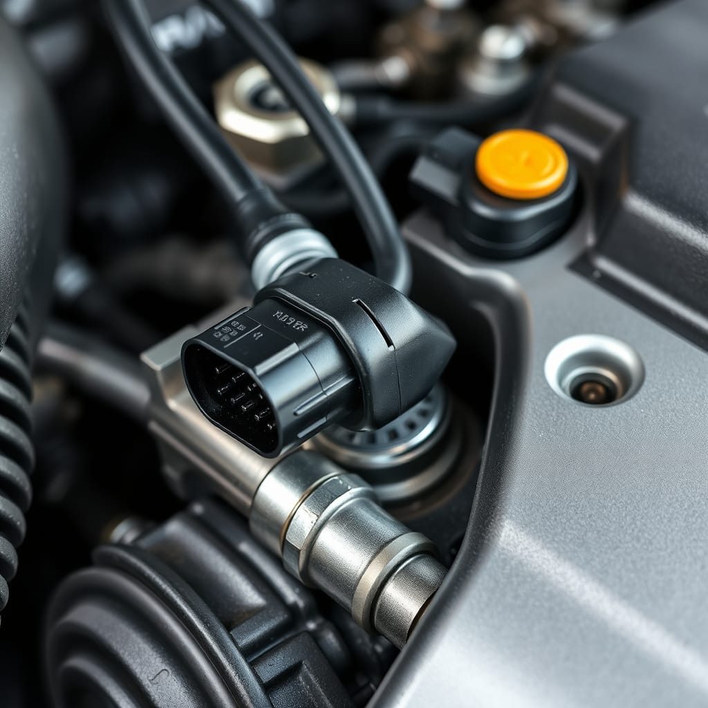
Step 3: Inspect the MAP Sensor and Connector
With the ignition off, locate the relevant sensor using vehicle-specific service information.
Inspect accessible wiring and connectors for:
Broken or frayed wires
Damaged insulation
Loose connectors
Corrosion
Moisture intrusion
Bent or damaged terminals
Signs of previous repairs
Correct any confirmed damage before performing more complex tests.
Step 4: Review MAP/BARO Live Data
Use a compatible scan tool to review available MAP or BARO data.
On suitable vehicles, key-on/engine-off readings can provide a useful comparison because intake manifold pressure should generally be close to local atmospheric pressure when the engine is not running.
However, displayed values may depend on sensor configuration, scan-tool interpretation, altitude, and the vehicle’s control strategy.
Compare the readings with the manufacturer’s expected values and other relevant data.
An implausible or fixed reading can guide further testing but does not prove sensor failure.
Step 5: Check Reference Voltage and Low-Reference Circuits
Use the manufacturer’s wiring diagram to identify the correct sensor terminals.
Where applicable, a qualified technician can check the reference-voltage supply and low-reference circuit.
Many conventional MAP sensors use a regulated reference supply, but specifications and pin arrangements differ.
If the reference supply is abnormal, investigate related wiring and shared circuits before replacing the MAP sensor.
Avoid shorting terminals or applying external voltage to the ECM circuit.
Step 6: Test the MAP Sensor Signal Circuit
Follow the manufacturer’s approved electrical-testing procedure.
Depending on the vehicle, diagnosis may include:
Measuring the signal at the correct terminals
Comparing sensor output with scan-tool data
Checking for a short to ground
Checking for an open circuit
Inspecting connector terminal integrity
Evaluating signal response under specified conditions
A low signal may originate from the sensor or from the external circuit.
Do not replace the sensor until testing distinguishes these possibilities.
Step 7: Check Sensor Response When Applicable
Some MAP sensor designs can be tested by comparing their output with controlled pressure or vacuum changes.
However, not every MAP sensor is suitable for handheld vacuum-pump testing.
Integrated sensors, turbocharged applications, and different sensor technologies may require specialized procedures or equipment.
Use only manufacturer-approved test methods and pressure limits.
Step 8: Investigate Intermittent Wiring Problems
If the fault is intermittent, inspect the harness routing and connector condition.
A qualified technician may perform manufacturer-approved circuit and connection checks while monitoring the relevant signal.
Avoid pulling or damaging wires during inspection.
Step 9: Confirm the Root Cause
Review the evidence before selecting a repair.
Determine whether the fault involves:
A defective MAP/BARO sensor
A shorted signal wire
An open or damaged circuit
A reference-voltage supply problem
A low-reference circuit problem
A damaged connector
A rare confirmed ECM/PCM fault
Repair only the cause supported by diagnostic testing.
Repair Options After Diagnosis
Replace a Confirmed Faulty MAP Sensor
If vehicle-specific testing confirms that the MAP sensor is defective, replace it with a compatible component.
Follow the manufacturer’s installation and calibration procedures where applicable.
Do not replace the sensor based only on the presence of P0107.
Repair Damaged Wiring
If the signal, reference-voltage, or low-reference wiring is damaged, repair the confirmed fault using manufacturer-approved methods.
Ensure the harness is properly routed and protected from heat, abrasion, and moving components.
Repair or Replace Damaged Connectors
If connector corrosion, loose terminals, or physical damage is confirmed, repair or replace the affected connector components.
Verify that electrical connections are secure.
Correct a Reference-Voltage Problem
If testing identifies a reference-supply fault, investigate the associated circuit.
A shared reference-voltage problem may involve other sensors or wiring.
Avoid replacing multiple sensors without establishing the actual source of the fault.
Address a Confirmed ECM/PCM Fault
ECM or PCM repair or replacement should only be considered after manufacturer-specific testing establishes an internal module fault.
Replacement may require programming, configuration, or other vehicle-specific procedures.
How to Verify the P0107 Repair
After completing the confirmed repair:
Check that the sensor and electrical connector are correctly installed.
Confirm that repaired wiring is secured and protected.
Verify reference-voltage and signal operation using the specified procedure.
Review MAP/BARO scan-tool data under appropriate operating conditions.
Clear relevant trouble codes using a suitable scan tool.
Operate the vehicle under the conditions required for the relevant diagnostic monitor.
Confirm that P0107 does not return.
Check for related codes and verify normal engine operation.
If the code returns, continue diagnosis rather than repeatedly replacing components.
A check engine light that remains off immediately after clearing codes does not by itself confirm a successful repair.
Safety Considerations When Diagnosing P0107
Electrical and engine-running tests require appropriate precautions.
Park the vehicle securely on a level surface.
Keep hands, tools, and clothing away from moving belts, pulleys, and fans.
Be cautious around hot engine and exhaust components.
Operate the engine only in a properly ventilated environment.
Use suitable electrical-testing equipment.
Do not short reference-voltage or ECM signal terminals.
Do not apply external voltage to sensor circuits unless explicitly required by an approved procedure.
Avoid piercing or damaging wiring insulation unnecessarily.
Follow manufacturer instructions when disconnecting electrical components.
Seek qualified assistance if the required tests cannot be performed safely.
Vehicle-Specific Considerations for P0107
MAP/BARO sensor configurations vary between manufacturers and engine types.
Some vehicles use a separate MAP sensor, while others integrate pressure sensing with additional functions or components.
Naturally aspirated and turbocharged engines may also use different pressure-sensing arrangements.
Sensor terminal assignments, signal characteristics, reference-voltage specifications, and diagnostic thresholds are not universal.
Always consult vehicle-specific service information before identifying terminals, testing electrical circuits, or replacing parts.
Frequently Asked Questions
What does the P0107 code mean?
P0107 indicates that the engine computer has detected a low electrical input in the monitored manifold absolute pressure or barometric pressure sensor circuit.
It does not automatically mean the MAP sensor has failed.
What are the common symptoms of P0107?
Possible symptoms include an illuminated check engine light, rough idle, hesitation, reduced power, and occasional stalling.
Some vehicles may show few noticeable driving symptoms.
What causes the P0107 code?
Possible causes include a faulty MAP/BARO sensor, damaged wiring, a signal short to ground, reference-voltage problems, or connector faults.
An ECM or PCM fault is a less common possibility.
Can a vacuum leak cause P0107?
A vacuum leak can affect intake manifold pressure and engine operation, but it is not a typical direct cause of an electrical low-input fault.
Investigate the MAP/BARO circuit before assuming a vacuum leak is responsible.
Does P0107 mean I need to replace the MAP sensor?
No.
The sensor should only be replaced after appropriate testing confirms that it is defective.
Can I drive with the P0107 code?
Some vehicles may remain drivable, but the fault can be associated with hesitation, reduced power, or stalling.
If the engine stalls, loses significant power, or behaves unpredictably, stop driving and arrange appropriate inspection.
How is P0107 diagnosed?
Diagnosis involves confirming the code, reviewing related codes and live data, inspecting the sensor connector and wiring, and testing the relevant signal, reference-voltage, and low-reference circuits.
How do I know the repair worked?
Confirm that the sensor circuit operates correctly, review relevant scan-tool data, and verify that P0107 does not return after the applicable diagnostic monitor runs.
Final Checks
The P0107 code identifies a low electrical input in the monitored MAP/BARO pressure sensor circuit.
Although a defective sensor is one possible cause, wiring damage, short circuits, connector faults, and reference-voltage problems must also be considered.
Begin with code verification and simple inspections, then use manufacturer-specific electrical tests to identify the root cause.
Repair the confirmed problem and verify normal sensor operation before considering the diagnosis complete.